|
| |
TM 9-2320-364-20-3
2-2507
86
85
30
87
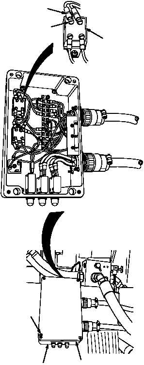
SCREWS
POWERBOX
COVER
(1) Disconnect wire 1734 from relay R35
terminal 86.
(2) Set multimeter select switch to volts DC.
(3) Connect positive (+) multimeter lead
to wire 1734.
(4) Connect negative (–) multimeter lead
to a known good ground.
(5) Turn ON engine switch
(TM 9-2320-364-10).
(a) If 22 to 28 vdc are not present,
perform Steps (6) below and repair
wire 1734 or notify DS Maintenance.
(b) If 22 to 28 vdc are present,
perform Steps (6), (7) and (8) below.
(6) Turn OFF ENGINE switch.
(7) Connect wire 1734 to relay R35 terminal
86.
(8) Install powerbox cover with four screws.
VOLTAGE TEST
Remove all jewelry such as rings, dog tags,
bracelets, etc. If jewelry or tools contact positive
electrical circuits, a direct short may result.
Damage to equipment, injury or death to
personnel may occur.
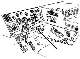
STEERING WHEEL
SHOWN REMOVED
FOR CLARITY
ENGINE SWITCH
TERMINAL 86
WIRE 1734
RELAY R35
|