|
| |
TM 9-2320-364-20-3
2-2567
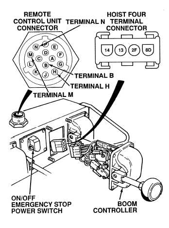
(1) Disconnect cable from remote control
unit (TM 9-2320-364-10).
(2) Remove BOOM controller from remote
control unit (Para 18-4).
(3) Set multimeter select switch to ohms.
(4) Turn ON remote control unit ON/OFF
EMERGENCY STOP switch.
(5) Is there continuity between remote
control unit hookup, terminal H and
four terminal connector, terminal 8D?
(a) If there is no continuity, repair
wire 8 between switch and four
terminal connector (see schematic
Fig 2-58) or notify DS
Maintenance.
(b) If there is continuity, go to Step (6)
below.
(6) Is there continuity between remote
control unit hookup, terminal B and
four terminal connector, terminal 2F?
(a) If there is no continuity, repair wire
2 (see schematic Fig 2-58) or
notify DS Maintenance.
(b) If there is continuity, go to Step (7)
below.
(7) Is there continuity between remote
control unit hookup, terminal N and
four terminal connector, terminal 13?
(a) If there is no continuity, repair wire
13 (see schematic Fig 2-58) or
notify DS Maintenance.
(b) If there is continuity, go to Step (8)
below.
(8) Is there continuity between remote
control unit hookup, terminal M and
four terminal connector, terminal 14?
(a) If there is no continuity, repair wire
14 (see schematic Fig 2-58) or
notify DS Maintenance.
(b) If there is continuity, go to Step 3
of this Fault.
CONTINUITY TEST
Remove all jewelry such as rings, dog tags, bracelets, etc. If jewelry or tools contact positive electrical
circuits, a direct short may result. Damage to equipment, injury or death to personnel may occur.
|