|
| |
TM 9-2320-364-20-3
2-2607
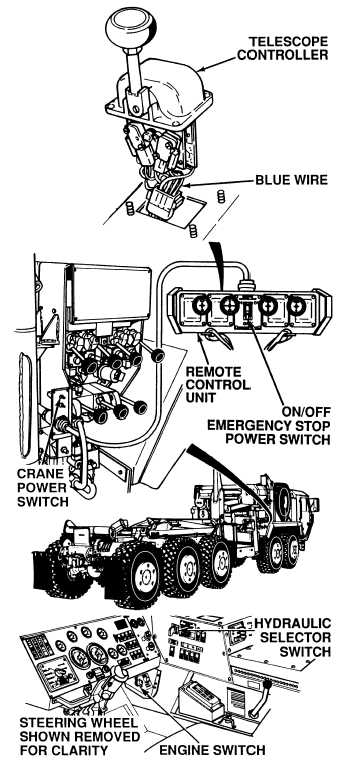
(1) Connect remote control unit to
remote control unit cable.
(2) Connect controller four terminal
connector to remote control unit
harness four terminal connector.
(3) Set multimeter select switch to
volts dc.
(4) Connect positive (+) multimeter
lead to blue wire terminal in four
terminal connector.
(5) Connect negative (–) multimeter
lead to a known good ground.
(6) Turn ON ENGINE switch
(TM 9-2320-364-10).
(7) Set hydraulic selector switch to
CRANE/SRW position.
(8) Set crane POWER switch to
ON position.
(9) Set remote control ON/OFF
EMERGENCY STOP power switch
to ON position.
(10) Hold TELESCOPE controller in the
IN position.
(a)
If 22 to 28 vdc are not present,
perform Step (11) below and
replace circuit card (Para 18-4).
(b)
If 22 to 28 vdc are present,
perform Steps (11) and (12) below.
(11) Set the following switches to the
OFF position: remote control
ON/OFF EMERGENCY STOP
power switch, crane POWER
switch, hydraulic selector switch and
ENGINE switch.
(12) Assemble remote control unit
(Para 18-4).
VOLTAGE TEST
Remove all jewelry such as rings, dog tags, bracelets, etc. If jewelry or tools contact positive electrical
circuits, a direct short may result. Damage to equipment, injury or death to personnel may occur.
|

