|
| |
TM 9-2320-364-20-3
2-1959
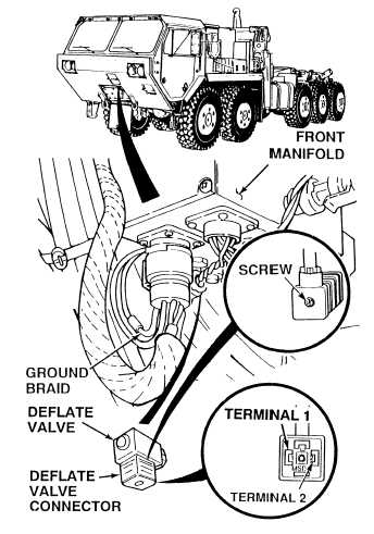
(1) Loosen screw and disconnect
deflate valve connector.
(2) Set multimeter select switch to
volts dc.
(3) Connect positive (+) multimeter lead
to deflate valve connector, terminal 2.
(4) Connect negative (–) multimeter
lead to front manifold ground braid.
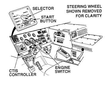
(5) Turn ON ENGINE switch
(TM 9-2320-364-10).
(6) Set CTIS controller to CROSS-
COUNTRY.
(7) Assistant pushes CTIS START
button.
(a)
If 22 to 28 vdc are not present,
turn OFF ENGINE switch and
replace front manifold
(Para 13-8).
(b)
If 22 to 28 vdc are present,
turn OFF ENGINE switch and
go to Step 5 of this Fault.
VOLTAGE TEST
Remove all jewelry such as rings, dog tags, bracelets, etc. If jewelry or tools contact positve electrical
circuits, a direct short may result. Damage to equipment, injury or death to personnel may occur.
(1) Set multimeter select switch to ohms.
(2) Is there continuity between deflate
valve connector, terminal 1 and front
manifold ground braid?
(a)
If there is no continuity, replace
front manifold (Para 13-8).
(b)
If there is continuity, go to
Step 6 of this Fault.
CONTINUITY TEST
|