|
| |
TM 9-2320-364-20-3
2-2787
(1) Set multimeter select switch to
diode test.
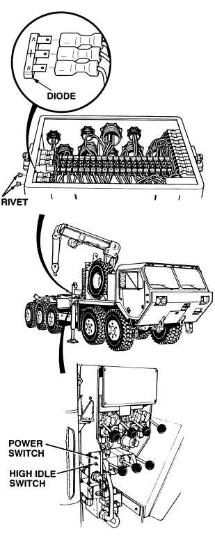
(2) Tag, mark and disconnect three
wires from diode.
(3) Connect negative (–) multimeter
lead to diode middle (+) terminal.
(4) Connect positive multimeter (+)
lead to each of the AC terminals,
one at a time.
(a) If any vdc are not present,
perform Steps (7) through (9)
below.
(b) If any vdc are present, go to
Step (5) below.
(5) Connect positive (+) multimeter
lead to diode middle (+) terminal.
(6) Connect negative multimeter (–)
lead to each of the AC terminals,
one at a time.
(a) If any vdc are present at either
terminal, perform Steps (7)
through (9) below.
(b) If any vdc are not present at
both terminals, perform Step
(9) below and go to Step 8 of
this Fault.
(7) Remove two rivets and diode
from junction box. Discard rivets
and diode.
(8) Install new diode with rivets.
(9) Connect three wires to diode.
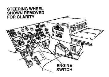
DIODE TEST
Remove all jewelry such as rings, dog tags, bracelets, etc. If jewelry or tools contact positive electrical
circuits, a direct short may result. Damage to equipment, injury or death to personnel may occur.
|