|
| |
TM 9-2320-364-20-4
12-201
c.
Adjustment.
Allow engine to cool before
performing troubleshooting or
maintenance. If necessary use
insulated pads and gloves. Hot
engine components will burn and
cause injury to personnel.
(1)
Drain air from No. 1 air tank.
(2)
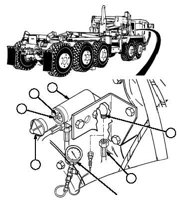
Disconnect air line 2159 (1) from
elbow (2).
(3)
Install air pressure gage on elbow (2).
(4)
Start engine.
(5)
Build air pressure until air dryer discharge
heard.
(6)
Shut OFF engine.
(7)
Check air pressure gage.
(a)
If air pressure gage indicates 121 to
psi (834 to 889 kPa), no adjustment
necessary, go to Step (16).
(b)
If air pressure gage indicates less than 121 psi (834 kPa) or more than 129 psi (889 kPa) go to Step
(8).
(8)
Remove cap (3) from governor (4).
(9)
Loosen nut (5) while holding adjusting
screw (6).
NOTE
One complete turn of adjusting screw will change adjustment approximately 15 psi
(103 kPa).
Turning adjusting screw counterclockwise will increase cut-out pressure.
Turning adjusting screw clockwise will decrease cut-out pressure.
(10)
Hold nut (5) and turn adjusting screw (6) to obtain 125 psi (862 kPa) cut-out pressure.
(11)
Hold adjusting screw (6) and tighten nut (5).
(12)
Install cap (3) on governor (4).
AIR PRESSURE
GAGE
3
1
2
5
4
6
|