|
| |
TM 9-2320-364-20-4
2-3105
2
1
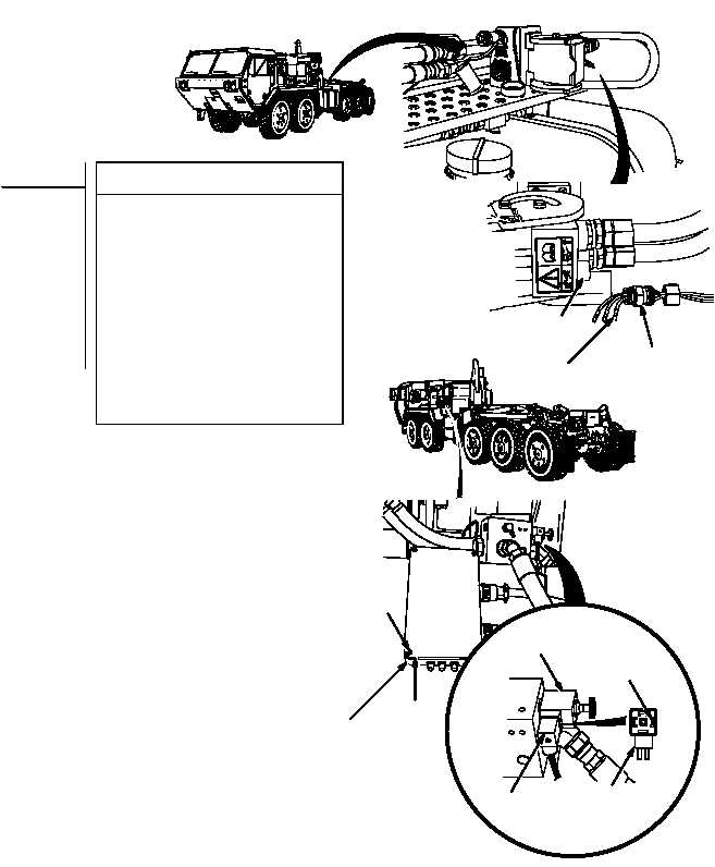
(1) Disconnect connector MC131 from quick
disconnect.
(2) Set multimeter select switch to OHMS.
(3) Is there continuity between connector
MC131 terminal C and connector MC134
terminal 2?
(a) If there is no continuity, repair wire
1435B (see schematic Fig 2-76)
or notify DS Maintenance.
(b) If there is continuity, wire 1435B
is OK.
(4) Connect connector MC131 to quick
disconnect.
(5) Connect connector MC134 to auxiliary
supply valve.
(6) Install cover on powerbox with four
screws.
CONTINUITY TEST
Remove all jewelry such as rings, dog tags, bracelets, etc. If jewelry or tools contact positive
electrical circuits, a direct short may result. Damage to equipment, injury or death to personnel
may occur.
QUICK
DISCONNECT
CONNECTOR
MC131
TERMINAL C
AUXILIARY
SUPPLY VALVE
CONNECTOR
MC134
CONNECTOR
MC134
TERMINAL 2
SCREWS
POWERBOX
COVER
|