|
| |
TM 9-2320-364-20-4
7-41
(2)
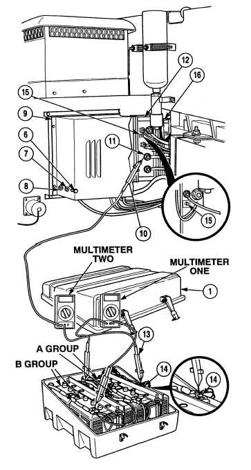
Remove four screws (6), lockwashers (7), washers (8) and DUVAC cover (9). Discard lockwashers.
Remove all jewelry such as rings, dog tags, bracelets, etc. If jewelry or tools contact positive
electrical circuits, a direct short may result. Damage to equipment, injury or death to personnel
may occur.
(3)
Connect multimeter two positive lead (10) to “A” terminal (11) of DUVAC controller (12) and
multimeter two negative lead (13) to negative terminal (14) of group “A” batteries.
(4)
With the aid of an assistant, start engine and run
engine at 800 to 1,000 RPM, (TM 9-2320-364
(5)
With the aid of an assistant, turn truck head
lights and heater on, (TM 9-2320-364-10).
Use caution when turning adjusting
screw of potentiometer. Turning
adjusting screw with too much
force may damage potentiometer.
NOTE
Potentiometer on DUVAC
controller is adjusted by
turning adjusting screw on
potentiometer. Turning to
the right increases voltage.
Turning to the left decreases
voltage.
Multimeter one should read
14.3 to 14.6 volts.
Multimeter two should read
26 to 30 volts.
(6)
Adjust potentiometer (15) on DUVAC
controller (12) as required.
(7)
Install DUVAC cover (9), four washers (8),
lockwashers (7) and screws (6).
(8)
Install battery box cover (1).
b.
Follow-On Maintenance:
Install left side noise panel, (Para 17-28).
Remove wheel chocks, (TM 9-2320-364-10).
END OF TASK
|