|
| |
TM 9-2320-364-20-4
7-88
7-21. ELECTRIC GAGE REPLACEMENT (CONT).
b.
Installation.
NOTE
Oil pressure gage, water temperature gage, transmission temperature gage and fuel gage
are all installed the same way. Water temperature gage shown.
Refer to Figure 7-1 for wire locations.
During installation make sure face of gage is aligned properly.
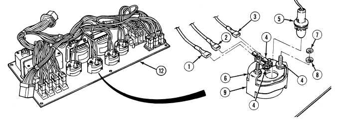
(1)
Position gage (6) in instrument panel (10).
(2)
Install gage mounting bracket (9) on rear of gage (6).
(3)
Install two lockwashers (8) and nuts (7) on rear of gage mounting bracket (9).
(4)
Install light socket 1052 (5) in rear of gage (6).
(5)
Install wires 1320 (1), 1435 (2) and 1276 (3) on terminals (4).
c.
Follow-On Maintenance:
Install instrument panel, (Para 7-13).
Start engine, (TM 9-2320-364-10).
Check operation, (TM 9-2320-364-10).
Shut OFF engine, (TM 9-2320-364-10).
Remove wheel chocks, (TM 9-2320-364-10).
END OF TASK
|