|
| |
TM 9-2320-364-20-4
7-104
Materials/Parts
Tags, Identification (Item 88, Appendix C)
This task covers:
a. Removal
b. Installation
c. Follow-On Maintenance
INITIAL SETUP
Equipment Condition
Engine OFF, (TM 9-2320-364-10)
Wheels chocked, (TM 9-2320-364-10)
Batteries disconnected, (Para 7-87)
Heater compartment cover removed,
(Para 17-4)
Tools and Special Tools
Tool Kit, General Mechanic’s: Automotive
(Item 74, Appendix G)
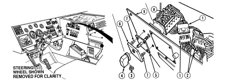
7-31. HYDRAULIC SELECTOR SWITCH REPLACEMENT.
a.
Removal.
NOTE
Connectors are disconnected by gently prying up on tab and pulling connectors apart.
(1)
Disconnect MC93 connector (1).
(2)
Disconnect MC94 connector (2).
(3)
Loosen screw (3) and remove knob (4) from hydraulic selector switch front mounting plate (5).
NOTE
Hydraulic selector switch face plate snaps in place.
(4)
Remove hydraulic selector switch face plate (6) from hydraulic selector switch front mounting plate (5).
(5)
Remove four screws (7), hydraulic selector switch front mounting plate (5) and hydraulic selector
switch (8) from heater control left side panel (9).
|