|
| |
9-13
NOTE
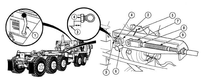
Measurement should be approximately 1-41/64 in. (42 mm) when transfer case is in neutral.
(2)
Measure shift rod (2) extension from transfer case housing (3) to rear of shift rod jam nut (4).
(3)
Remove cotter pin (5) from clevis pin (6). Discard cotter pin.
(4)
Remove clevis pin (6) from yoke (7).
(5)
Loosen jam nut (8) on transfer case shift cable (9).
(6)
With the aid of an assistant, hold transfer case shift lever (1) in Neutral (straight up) position and screw
yoke (7) in or out to align holes in yoke and shift rod (2).
(7)
Install clevis pin (6) in yoke (7) and shift rod (2).
(8)
Install cotter pin (5) in clevis pin (6).
NOTE
Transfer case shift lever should not hit electronic control box when shifting into high or low
range.
(9)
Move transfer case shift lever (1) through low, neutral and high to make sure that shift rod (2) is free to
fully engage the lock positions.
(10)
Set transfer case shift lever (1) to high range.
(11)
Tighten jam nut (8) securely against yoke (7).
b.
Follow-On Maintenance:
Start engine, (TM 9-2320-364-10).
Check transfer case operation, (TM 9-2320-364-10).
Shut OFF engine, (TM 9-2320-364-10).
Remove wheel chocks, (TM 9-2320-364-10).
END OF TASK
1–41/64
IN.
(42 MM)
|