|
| |
TM 9-2320-364-20-5
14-26
14-9. GEAR BOX STEERING SHAFT REPAIR (CONT).
d.
Assembly.
NOTE
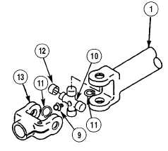
Rod end clevis and yoke end cross and bearing assemblies are installed the same way.
Rod end clevis shown.
(1)
Position cross and bearing assembly (10) and
rod end clevis (13) in steering shaft (1).
Use caution when installing
bearing assemblies. Needles in
bearing assemblies may become
lost or damaged.
(2)
Install four bearing assemblies (12) in
steering shaft (1) and rod end clevis (13).
Use care when installing retaining rings. Retaining rings are under spring tension and can
act as projectiles when released and could cause severe eye injury.
(3)
Install four retaining rings (11) on cross and bearing assembly (10).
(4)
Install lube fitting (9) on cross and bearing assembly (10).
(5)
Repeat Steps (1) through (4) for yoke end cross and bearing assembly installation.
|