|
| |
TM 9-2320-364-20-5
15-15
This task covers:
a. Torquing Procedure
b. Follow-on Maintenance
INITIAL SETUP
Personnel Required
Three
Equipment Condition
Engine OFF, (TM 9-2320-364-10)
Wheels chocked, (TM 9-2320-364-10)
Tools and Special Tools
Tool Kit, General Mechanic’s: Automotive
(Item 74, Appendix G)
Socket Set, 3/4 in. (Item 61, Appendix G)
Wrench, Combination 1-1/8 in.
(Item 79, Appendix G)
Adapter, Torque (Appendix D)
15-6. FRONT TANDEM CROSSMEMBER TORQUING PROCEDURE.
a.
Torquing Procedure.
Torque wrench must be installed in straight line with torque adapter or improper torque may
be applied. Failure to comply may result in damage to equipment.
NOTE
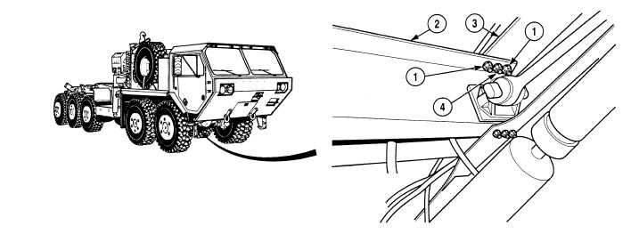
Both sides of front tandem crossmember are tightened the same way. Right side shown.
Front tires may be turned as necessary to accommodate torque wrench.
(1)
With the aid of assistants and using torque adapter, tighten two nuts (1) on crossmember (2) and gusset (3)
to 305 lb-ft (414 N.m).
(2)
With the aid of assistants and using torque adapter, tighten nut (4) on crossmember (2) and gusset (3) to
165 lb-ft (224 N.m).
|