|
| |
TM 9-2320-364-20-5
17-12
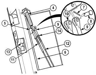
17-7. CAB DOOR ADJUSTMENT (CONT).
NOTE
Light upward pressure must be maintained on both outer link rod and cable assembly fitting
for proper alignment.
(7)
While pulling up on outer link rod (11),
adjust clevis (10) by turning clockwise or
counterclockwise until clevis aligns with hole
in rotary lock arm (5).
(8)
Install outer link rod (11) in rotary lock
arm (5) with pin (8) and cotter pin (7), and
tighten jam nut (14).
(9)
Loosen jam nut (14) on cable assembly (12).
(10)
While pulling up on cable assembly (12),
adjust clevis (9) by turning clockwise or
counterclockwise until clevis aligns with
hole in rotary lock arm (5).
(11)
Install clevis (9) with pin (8) and cotter
pin (7) on rotary lock arm (5).
NOTE
Use care when installing spring.
Spring may fall between inner
skin and door.
(12)
Install spring (4) on door frame (6) and
rotary lock arm (5).
(13)
Tighten jam nut (14) on cable
assembly (12).
(14)
Unlatch door rotary lock (13).
(15)
Shut door and check rotary lock (13)
operations.
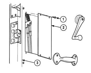
(16)
Install inspection cover (2) with four
screws (1) on inner skin assembly (3).
b.
Follow-On Maintenance:
Lubricate dovetail and door rotary lock,
(TM 9-2320-364-10).
Remove wheel chocks, (TM 9-2320-364-10).
END OF TASK
|