|
| |
TM 9-2320-364-20-5
17-95
Materials/Parts
Clip, Push (6) (Item 24, Appendix F)
Locknut (2) (Item 91, Appendix F)
Locknut (4) (Item 106, Appendix F)
Locknut (3) (Item 140, Appendix F)
Screw, Self-Tapping (Item 313, Appendix F)
This task covers:
a. Removal
c. Installation
d. Follow-On Maintenance
b. Cleaning/Inspection
INITIAL SETUP
Personnel Required
Two
Equipment Condition
Engine OFF, (TM 9-2320-364-10)
Wheels chocked, (TM 9-2320-364-10)
Center mud flap removed, (Para 17-38)
Rear fender side marker lamp
removed, (Para 7-48)
Rear fender reflector removed, (Para 19-2)
Tools and Special Tools
Tool Kit, General Mechanic’s: Automotive
(Item 74, Appendix G)
17-35. REAR FENDER AND FENDER SUPPORT ARM REPLACEMENT.
a.
Removal.
NOTE
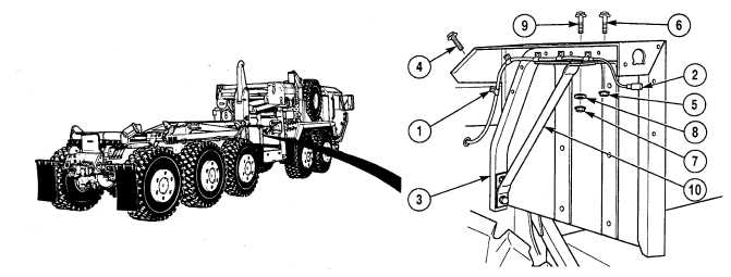
Push clips are removed by first pulling out lock button, then removing clip.
(1)
Remove six push clips (1) and marker lamp wiring harness (2) from fender support arm (3). Discard
push clips.
(2)
Remove self-tapping screw (4) from fender support arm (3). Discard self-tapping screw.
(3)
Remove two locknuts (5) and screws (6) from fender support arm (3). Discard locknuts.
(4)
Remove locknut (7), washer (8) and screw (9) from fender support arm (3) and fender brace (10). Discard
locknut.
|