|
| |
TM 9-2320-364-20-5
19-55
(2)
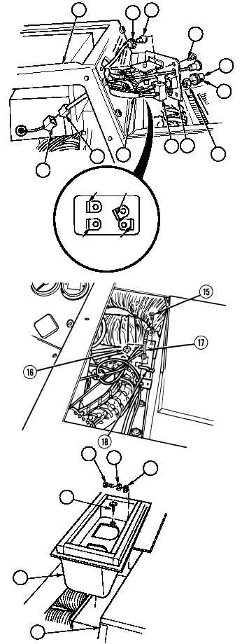
Disconnect connector (3) from
connector (4).
(3)
Remove four screws (5) and pull heater
control panel (6) out from heater
compartment (7).
(4)
Remove lamp socket (8) from heater
panel (6).
(5)
Remove lamp (9) from lamp socket (8).
(6)
Remove wires 1082, red, brown and orange
(10) from switch (11).
(7)
Loosen screw (12) and remove knob (13)
from switch (11).
(8)
Remove nut (14) and switch (11) from heater
control panel (6).
(9)
Remove screw (15), nut (16) and DEF/CAB
control cable (17) from lever (18).
(10)
Remove three screw and washer assemblies
(19) from upper plenum (20). Discard
screw and washer assemblies.
(11)
Remove two screws (21), washer (22),
lockwasher (23) and upper plenum (20)
from heater (24). Discard lockwasher.
19
20
24
21
22
23
ORANGE
RED
WIRE 1082 BROWN
7
8
9
5
12
14
6
11
10
3
4
13
|

