|
| |
TM 9-2320-364-20-5
19-61
(13)
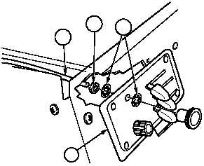
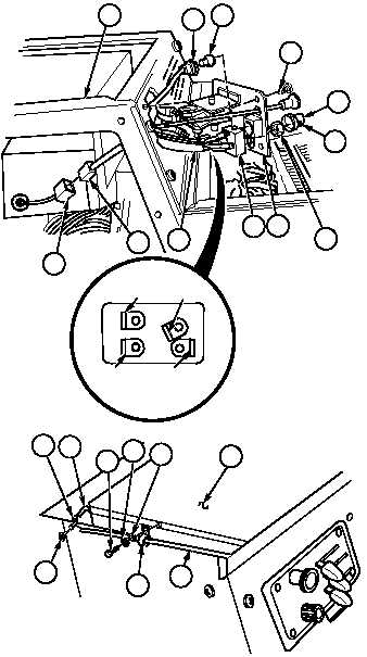
Install nut (31) and lockwasher (32) on
cabin/ventilator cable (29).
(14)
Install cabin/ventilator cable (29) on control
bracket (6) with lockwasher (32) and nut
(31).
(15)
Install switch (11) and nut (14) on heater
control panel (6).
(16)
Install wires 1082, red, brown and
orange (10) on switch (11).
(17)
Install knob (13) on switch (11) and tighten
screw (12).
(18)
Install lamp (9) in lamp socket (8).
(19)
Install lamp socket (8) in heater control
panel (6).
(20)
Install heater control panel (6) on heater
compartment (7) with four screws (5).
(21)
Connect connector (4) to connector (3).
(22)
Install cabin/ventilator cable (29) on
damper (31) with two push on nuts (30).
(23)
Install cabin/ventilator cable (29) on heater
(24) with clip (28), screw (25), lockwasher
(26) and washer (27).
27
28
24
26
25
31
30
30
29
31
6
32
29
ORANGE
RED
WIRE 1082 BROWN
7
8
9
5
12
14
6
11
10
3
4
13
|