|
| |
TM 9-2320-364-20-5
13-33
(16)
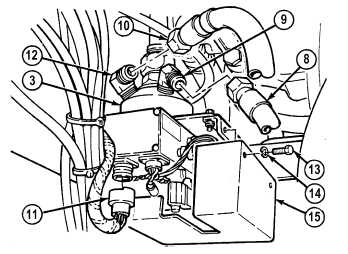
Connect connector (12) to CTIS front
manifold (3).
(17)
Install CTIS front manifold valve cover
(15) on CTIS front manifold (3) with three
lockwashers (14) and screws (13). Tighten
screws to 75 lb-in (8 N.m).
(18)
Install hose 2098 (10) on elbow (11).
(19)
Install hose 2096 (8) on elbow (9).
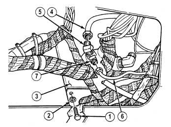
(20)
Install air line 2993 (6) on fitting (7).
(21)
Install air line 2074 (4) on fitting (5).
(22)
Install screw (1) and lockwasher (2) in
CTIS front manifold (3). Tighten screw
to 75 lb-in (8 N.m).
c.
Follow-On Maintenance:
Connect batteries, (Para 7-87).
Start engine, (TM 9-2320-364-10).
Build up air pressure to 125 psi (861 kPa).
Shut OFF engine, (TM 9-2320-364-10).
Operate CTIS and check for air leaks, (TM 9-2320-364-10).
Close front access cover, (TM 9-2320-364-10).
Install Electronic Control Box (ECB) right side panel, (Para 17-21).
Remove wheel chocks, (TM 9-2320-364-10).
END OF TASK
|