|
| |
TM 9-2320-364-20-5
21-75
b.
Installation.
NOTE
Connect only wires required to complete task. Refer to the electrical schematic drawing
3123995 and Table 21-1 Powerbox Wiring for specific powerbox wiring replacement.
(1)
Follow Table 21-1 to connect wires.
(2)
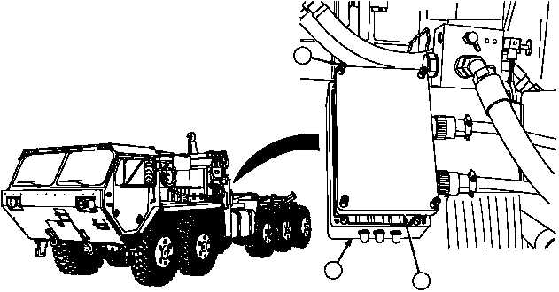
Position cover (2) on power box (3).
(3)
Tighten four screws (1) on cover (2).
c.
Follow-On Maintenance:
Connect batteries, (Para 7-87).
Remove wheel chocks, (TM 9-2320-364-10).
END OF TASK
1
3
2
|

