Order this information in Print

Order this information on CD-ROM

Download in PDF Format


Click here to make tpub.com your Home Page

Page Title: Pressure relief valve
Back | Up | Next

Click here for a printable version

Google


Web
www.tpub.com

Home


Information Categories
.... Administration
Advancement
Aerographer
Automotive
Aviation
Combat
Construction
Diving
Draftsman
Engineering
Electronics
Food and Cooking
Math
Medical
Music
Nuclear Fundamentals
Photography
Religion
USMC
   
Products
  Educational CD-ROM's
Printed Manuals
Downloadable Books


TM 9-2320-364-34-2      12-11 (10) 
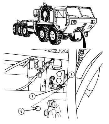
Remove pressure relief valve 12A cover (6). NOTE Turning pressure relief valve set screw to the right will increase pump output pressure and turning to the left will decrease pump output pressure.  Each full turn will change the output pressure about 400 psi (2,758 kPa). (11) Loosen nut (7) and adjust pressure with set screw (8). (12) Tighten nut (7) on set screw (8). (13) Start engine. (14) Verify pressure and make necessary adjustments.  Refer to Steps (6) through (13). (15) Repeat Steps (6) through (13) until 2,000 psi (13,790 kPa) present when load valve is fully closed. (16) Shut OFF engine. (17) Install relief valve cover (6). NOTE Do not remove flow meter at this time. (18) Go to Step d.

Privacy Statement - Press Release - Copyright Information. - Contact Us - Support Integrated Publishing

Integrated Publishing, Inc. - A (SDVOSB) Service Disabled Veteran Owned Small Business