|
| |
TM 9-2320-364-34-2
12-54
12-8. STEERING SYSTEM ALIGNMENT AND ADJUSTMENT (CONT).
(6)
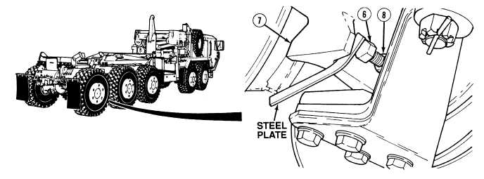
Place a 1/8 by 1 by 8 in. steel plate between right Axle No. 5 steering stop bolt (6) and hub assembly (7).
(7)
Loosen nut (8).
(8)
Adjust steering stop bolt (6) and nut (8) so stop bolt touches the steel plate.
(9)
With the aid of an assistant, turn the steering wheel full left.
NOTE
It may be necessary to rotate jamnut right or left 1/2 flat to permit installation of deep well
socket on nut.
(10)
Tighten nuts (1) and (8) to 147 lb-ft (199 N.m).
(11)
With the aid of an assistant, turn the steering wheel to the left until the rear side of the left front tire is 2
1/2 in. (63.5 mm) away from the suspension beam.
(12)
If 2 1/2 in. (63.5 mm) cannot be attained, loosen nut (8) and turn steering stop bolt (6) until it bottoms
out.
(13)
Repeat Steps (11) and (12) for Axle No. 2.
|