|
| |
TM 9-2320-364-34-2
12-77
(3)
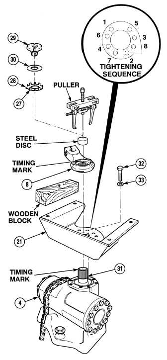
Install bracket (21) on steering gear (4) with
eight lockwashers (33) and screws (32).
Tighten screws to 160 to 170 lb-ft (217 to
231 N.m) in sequence shown. Recheck
torques.
NOTE
Ensure timing marks are aligned
as prior to removal.
(4)
Align timing marks and install pitman
arm (8) on shaft (31).
Adhesives, solvents and sealing
compounds can burn easily, can
give off harmful vapors and are
harmful to skin and clothing. To
avoid injury or death, keep away
from open fire and use in a well-
ventilated area. If adhesive,
solvent or sealing compound gets
on skin or clothing, wash
immediately with soap and water.
(5)
Coat retainer (29) with antiseize compound.
(6)
Position locking ring (28), spacer (30) and
retainer (29) as one assembly on pitman
arm (8).
(7)
Bend two opposing tabs (27) on locking ring
(28) into pitman arm (8).
NOTE
Wooden block used in Step (7)
should be 2 by 4 by 12 in.
(8)
Wedge wooden block between pitman
arm (8) and bracket (21).
(9)
Tighten retainer (29) to 450 lb-ft (610 N.m).
(10)
Bend two opposing tabs (27) on locking
ring (28) down into next available slot on
retainer (29).
NOTE
Retainer may have to be
tightened slightly to align tabs
with slots.
(11)
Remove wooden block from pitman arm (8)
and bracket (21).
|

