|
| |
TM 9-2320-364-34-2
3-118
Materials/Parts
Oil, Lubricating (Item 38, Appendix B)
Tape, Masking (Item 73, Appendix B)
Lock, Valve (32) (Item 162, Appendix E)
Seal, Oil (32) (Item 595, Appendix E)
This task covers:
a. Removal
b. Installation
c. Follow-On Maintenance
INITIAL SETUP
Equipment Condition
Engine OFF, (TM 9-2320-364-10)
Wheels chocked, (TM 9-2320-364-10)
Cylinder head removed, (Para 3-7)
Exhaust valve bridges removed, (Para 3-17)
Tools and Special Tools
Tool Kit, General Mechanic’s
(Item 240, Appendix F)
Compressor Unit, Air (Item 35, Appendix F)
Compressor Spring, Valve (Item 41, Appendix F)
Gloves, Heavy Duty (Item 82, Appendix F)
Goggles, Industrial (Item 83, Appendix F)
Gun, Airblow (Item 86, Appendix F)
Hammer, Hand, Soft Plastic
(Item 88, Appendix F)
Installer, Guide, Valve (Item 108, Appendix F)
Wooden Blocks (2) (Appendix C)
3-18. EXHAUST VALVE REPLACEMENT.
a.
Removal.
NOTE
All 32 exhaust valves are removed the same way.
Number each valve upon removal to ensure installation in same location.
Repeat Steps (1) through (6) for each valve being removed.
Wooden blocks under valve will support valve while two-piece valve lock is being removed.
(1)
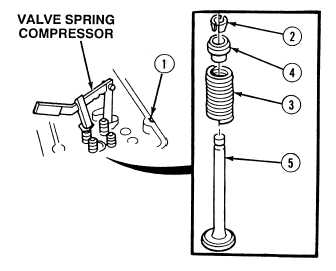
Position cylinder head (1) on wooden blocks.
(2)
Install valve spring compressor on cylinder head (1).
Use care when removing springs.
Springs are under tension and can
act as projectiles when released
and could cause injury to
personnel.
(3)
Remove and discard two-piece valve lock
(2) by compressing spring (3) on spring cap
(4).
(4)
Release pressure on spring (3).
(5)
Remove spring cap (4) and valve spring (3)
from exhaust valve (5).
(6)
Remove spring compressor from cylinder
head (1).
|

