|
| |
TM 9-2320-364-34-2
6-8
6-2. ALTERNATOR ASSEMBLY REPAIR (145 AMP) (CONT).
b.
Testing.
(1)
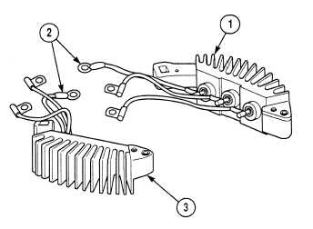
Touch negative (–) test lead to bare metal
surface on positive rectifier (1).
NOTE
If reading is not between 15-19
ohms for each terminal, rectifier
is defective. Replace rectifier.
(2)
Touch positive (+) test lead separately to
each of three eyelet terminals (2).
(3)
Touch positive (+) test lead to bare metal
surface on positive rectifier (1).
NOTE
If multimeter does not indicate
infinity in Step (4), positive
rectifier is defective. Replace
rectifier.
(4)
Touch negative (–) test lead separately to
each of three eyelet terminals (2).
(5)
Touch negative lead (–) to bare metal
surface on negative rectifier (3).
NOTE
If multimeter does not indicate
infinity, in Step (6), negative
rectifier is defective. Replace
rectifier.
(6)
Touch positive (+) test lead separately to
each of three eyelet terminals (2).
(7)
Touch negative lead (–) to bare metal
surface on negative rectifier (3).
NOTE
If reading is not between 15-19
ohms for each terminal, rectifier
is defective. Replace rectifier.
(8)
Touch negative (–) test lead separately to
each of three eyelet terminals (2).
|