|
| |
TM 9-2320-364-34-2
6-24
6-3. ALTERNATOR ASSEMBLY REPAIR (200 AMP) (CONT).
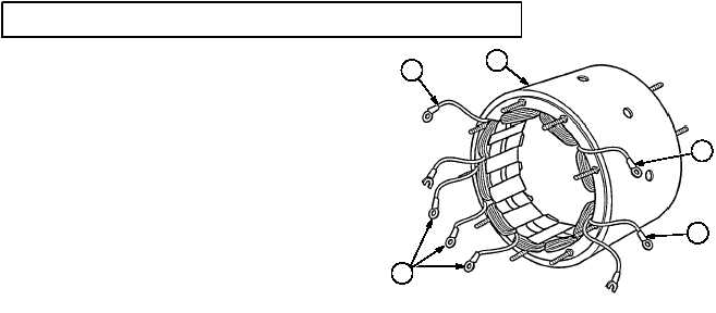
NOTE
200 amp alternator has two
stators. Three wires are for one
stator and the other three wires
are for remaining stator.
Perform Steps (3) and (4) for
each stator.
Multimeter should read zero
ohms between three wires in
each stator in Step (3). If ohm
meter does not read zero ohms,
stator is defective and alternator
housing must be replaced.
(3)
Check stators by touching two of three
stator wires (3) with test leads. Test each
combination of all wires in each stator.
NOTE
Multimeter should read infinity in
Step (4). If any reading is not
infinity, stator is grounded and
alternator housing must be
replaced.
(4)
Check stators by touching one test lead to
each wire (3) and other test lead to
alternator housing (4).
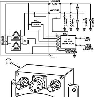
NOTE
Each terminal should show
continuity. Refer to Table 6-1
and alternator schematic.
(5)
Test front housing (5) continuity by setting
multimeter to x10 range and touching two
control unit connector terminals at a time.
Test each combination of terminals to ensure
all internal wiring is intact.
6
3
3
3
3
Table 6-1. PIN ASSIGNMENTS, REGULATOR
CONNECTOR, ON ALTERNATOR
CONNECTOR
PIN
A
B
C
D
E
MEASURE
TO:
+24 v Stud
C
Gnd
+24 v Stud
+12 v Stud
METER
READING
More than 2 ohms
but less than 3 ohms
(Field Coil)
1.5k ohms
Less than .1 ohms
Less than .1 ohms
Less than .1 ohms
ALTERNATOR SCHEMATIC
7
|