|
| |
TM 9-2320-364-34-3
13-52
Materials/Parts
Cable Ties (Item 9, Appendix B)
Sealing Compound (Item 54, Appendix B)
Locknut (12) (Item 166, Appendix E)
Locknut (4) (Item 167, Appendix E)
Locknut (4) (Item 169, Appendix E)
Locknut (5) (Item 176, Appendix E)
Locknut (2) (Item 201, Appendix E)
Locknut (6) (Item 210, Appendix E)
Lockwasher (Item 275, Appendix E)
Pin, Cotter (Item 420, Appendix E)
This task covers:
a. Removal
b. Installation
c. Follow-On Maintenance
INITIAL SETUP
Personnel Required
Two
Equipment Condition
Engine OFF, (TM 9-2320-364-10)
Wheels chocked, (TM 9-2320-364-10)
Air cleaner skirt removed, (TM 9-2320-364-20)
Cooling skirt removed, (TM 9-2320-364-20)
Air cleaner assembly removed,
(TM 9-2320-364-20)
Slave receptacle removed, (TM 9-2320-364-20)
DUVAC panel removed (145 AMP only),
(TM 9-2320-364-20)
Polarity protection control panel removed
(200 AMP only), (TM 9-2320-364-20)
Battery box wiring removed,
(TM 9-2320-364-20)
Steering reservoir removed,
(TM 9-2320-364-20)
Engine/transmission removed, (Para 3-4)
Tools and Special Tools
Tool Kit, General Mechanic’s
(Item 240, Appendix F)
Wrench Set, Socket 3/4 in. Drive
(Item 274, Appendix F)
Wrench, Torque (0 to 175 lb-ft [0-237 N.m])
(Item 277, Appendix F)
Lifting Device, Minimum 300 lbs (136 kg)
13-12. LEFT SIDE POWER MODULE FRAME REPLACEMENT.
Note location of cable ties and remove as required.
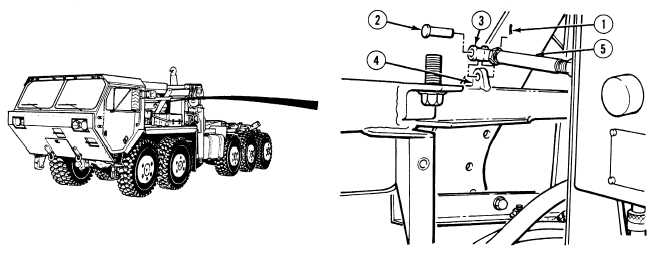
(1)
Remove cotter pin (1), pin (2) and clevis (3) from power module frame (4). Discard cotter pin.
(2)
Position clevis rod assembly (5) clear of the power module frame (4).
|