|
| |
TM 9-2320-364-34-3
13-11
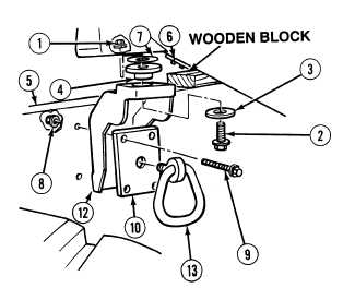
NOTE
Number of spacers vary. Note
number of spacers prior to
removal.
(3)
Remove spacer (7) from mount (4).
(4)
With the aid of an assistant, remove four
locknuts (8), screws (9), ring bracket (10)
and rear cab mounting bracket (12) from
frame (5). Discard locknuts.
(5)
Remove mount (4) from rear cab mounting
bracket (12).
(6)
Remove tie down ring (13) from ring
bracket (10).
b.
Installation.
(1)
Install tie down ring (13) in ring
bracket (10).
(2)
Spray soap solution on cab mount (4) and
rear cab mounting bracket (12).
(3)
Install cab mount (4) in rear cab mounting bracket (12).
NOTE
Install number of spacers as noted prior to removal.
(4)
Position spacers (7) on mount (4).
(5)
With the aid of an assistant, install rear cab mounting bracket (12) and ring bracket (10) on frame (5)
with four screws (9) and locknuts (8).
Cab weighs 1,700 lbs (772 kg). Use hydraulic jack prior to installation to prevent possible
injury to personnel.
(6)
Using hydraulic jack raise rear of cab and remove block between frame (5) and crosstube (6).
(7)
Lower rear of cab on rear cab mount (4).
(8)
Install washer (3) and screw (2) to rear mount (4) with locknut (1).
c.
Follow-On Maintenance:
Remove wheel chocks, (TM 9-2320-364-10).
END OF TASK
|