|
| |
TM 9-2320-364-34-3
13-13
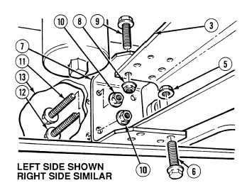
(3)
Remove eight locknuts (5) and screws (6)
from bottom of front crossmember (3) and
two front crossmember brackets (7).
Discard locknuts.
NOTE
To remove upper locknuts
and screws, place socket on
upper locknuts and insert a
extension through the
bottom bolt holes into the
socket.
Front crossmember bracket
bolts may have to be
loosened 1/2 in. (12.7 mm)
so extension can fit through
bottom bolt holes.
(4)
With the aid of an assistant, remove eight
locknuts (8), screws (9) and front
crossmember (3) from two front
crossmember brackets (7). Discard locknuts.
(5)
With the aid of an assistant, remove eight
locknuts (10), four screws (11), four
screws (12) and front crossmember brackets
(7) from frame (13). Discard locknuts.
b.
Installation.
(1)
Install front crossmember brackets (7) on
frame (13) with four screws (11), four
screws (12) and eight locknuts (10).
(2)
With the aid of an assistant, position front
crossmember (3) in front crossmember
brackets (7) with eight screws (9) and
locknuts (8).
(3)
With the aid of an assistant, install eight
screws (6) in bottom of front crossmember
brackets (7) and front crossmember (3) with
eight locknuts (5).
(4)
With the aid of an assistant, tighten eight
locknuts (8) on screws (9).
|