|
| |
TM 9-2320-364-34-4
20-49
Materials/Parts
Cable Ties (Item 9, Appendix B)
Tags, Identification (Item 72, Appendix B)
This task covers:
a. Removal
b. Follow-On Maintenance
INITIAL SETUP
Equipment Condition
Blower assembly removed, (Para 20-13)
Tools and Special Tools
Tool Kit, General Mechanic’s
(Item 240, Appendix F)
20-14. ENGINE BRAKE RETARDER REMOVAL.
a.
Removal.
Pull back protective sleeve on positive lock connectors prior to removing positive lock connectors.
Do not pull on wires of harness to remove positive lock connectors. Failure to comply may result
in damage to solenoid and/or harness.
NOTE
There are two supply brakes
and two drones on each
cylinder bank. All supply
brakes and drones are
removed the same way.
Right cylinder bank shown.
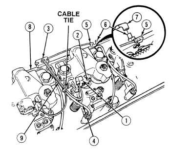
Note location of cable ties
and remove as required.
Tag and mark wires prior to
removal.
(1)
Disconnect positive lock connectors (1)
from engine brake solenoids (2).
(2)
Remove rubber harness support (3) from
injector lines (4).
(3)
Disconnect spade connector (5) from
terminal assembly (6).
(4)
Disconnect spade connector (7) from
terminal assembly (6).
(5)
Remove terminal assembly (6) from
cylinder head (8).
(6)
Remove engine brake harness (9) from
cylinder head (8).
|