|
| |
TM 9-2320-364-34-4
20-95
NOTE
Tag and mark position and
location of each connecting rod
and piston prior to removal.
(6)
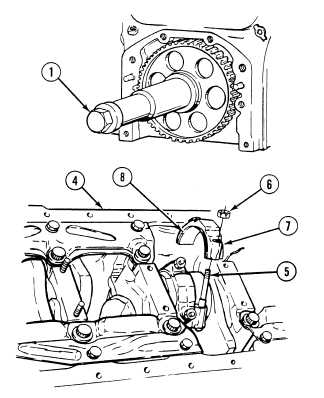
Position engine block (4) in stand with
bottom facing up.
(7)
Turn screw (1) to allow access to bearing
cap screws (5).
(8)
Remove two nuts (6) from bearing cap
screws (5).
(9)
Remove connecting rod bearing cap (7) and
lower bearing shell (8).
Ensure connecting rod does
not catch on lip of liner or
damage to liner may result.
Ensure connecting rod does
not strike inside edge of
piston or damage to piston
may result.
NOTE
Cylinder liner may come out with
piston.
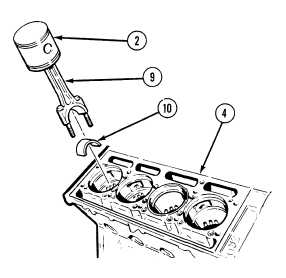
(10)
Position engine block (4) in stand with
bottom facing down.
(11)
With aid of assistant remove piston (2),
connecting rod (9) and upper bearing
shell (10) as an assembly from engine
block (4).
|