|
| |
TM 9-2320-364-34-4
20-266
Materials/Parts
Lockwasher (6) (Item 292, Appendix E)
Shim (2) (Item 632, Appendix E)
Shim (2) (Item 633, Appendix E)
Shim (2) (Item 634, Appendix E)
This task covers:
a. Installation
b. Follow-On Maintenance
INITIAL SETUP
Equipment Condition
Flywheel housing and rear oil seal installed,
(Para 20-76)
Tools and Special Tools
Tool Kit, General Mechanic’s
(Item 240, Appendix F)
Indicator, Dial, Set w/Magnetic Base
(Item 98, Appendix F)
Wrench, Crowsfoot, 9/16 in., 3/8 in. Drive
(Item 269, Appendix F)
Wrench Set, Socket 3/8 in. Drive
(Item 273, Appendix F)
Wrench, Torque (0 to 60 N.m)
(Item 276, Appendix F)
Wrench, Torque (0 to 175 lb-ft [0-237 N.m])
(Item 277, Appendix F)
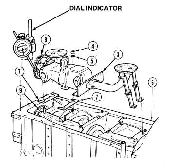
20-77. ENGINE OIL PUMP ASSEMBLY INSTALLATION.
a.
Installation.
NOTE
If shims were damaged during
removal, ensure shims of same
thickness as recorded during
removal are used for installation.
(1)
Install shims (7) on studs in engine
block (6).
(2)
Position oil pump (3) on engine block (6).
(3)
Install four lockwashers (5) and nuts (4) on
studs in engine block (6). Tighten nuts to
27 lb-ft (37 N.m).
NOTE
Each 0.005 in. (0.127 mm)
shim changes gear backlash
0.0035 in. (0.088 mm).
Backlash should be 0.006 to
0.012 in. (0.152 to 0.30 mm).
(4)
Using a dial indicator, measure backlash
between crankshaft oil pump drive gear (8)
and oil pump drive gear (9). Add or
subtract same thickness of shims (7) under
pump to obtain correct backlash.
|