|
| |
TM 9-2320-364-34-4
20-306
This task covers:
a. Exhaust Valve Clearance Adjustment
c. Fuel Injector Timing Adjustment
b. Engine Brake Retarder Adjustment
d. Follow-On Maintenance
INITIAL SETUP
Equipment Condition
Engine brake retarders installed, (Para 20-93)
Tools and Special Tools
Tool Kit, General Mechanic’s
(Item 240, Appendix F)
Gage, Feeler (Item 77, Appendix F)
Gage, Feeler, Jacobs Brake
(Item 78, Appendix F)
Gage, Timing, Injector (Item 80, Appendix F)
Wrench Set, Pushrod (Item 272, Appendix F)
Wrench, Torque (0 to 175 lb-ft [0-237 N.m])
(Item 277, Appendix F)
20-94. ENGINE TUNE-UP ADJUSTMENTS.
a.
Exhaust Valve Clearance Adjustment.
Crankshaft must be turned clockwise only. If crankshaft is turned counterclockwise, crankshaft
screw will be loosened resulting in damage to equipment.
NOTE
Two push rods operate four exhaust valves for each of eight cylinders. All 16 exhaust valve
clearance adjustments are made the same way.
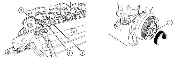
(1)
Rotate crankshaft by turning pulley (1) clockwise until engine is on injection stroke. This can be noted
when injector push rod (2) is fully up, and exhaust push rods (3) are down.
|