|
| |
TM 9-2320-364-34-4
20-351
Materials/Parts
Gasket (2) (Item 87, Appendix E)
Locknut (5) (Item 191, Appendix E)
Stud (8) (Item 677, Appendix E)
This task covers:
a. Installation
b. Follow-On Maintenance
INITIAL SETUP
Equipment Condition
ECM installed, (Para 20-104)
Tools and Special Tools
Tool Kit, General Mechanic’s
(Item 240, Appendix F)
Stud Remover and Setter (Item 231, Appendix F)
Wrench, Torque (0 to 175 lb-ft [0-237 N.m])
(Item 277, Appendix F)
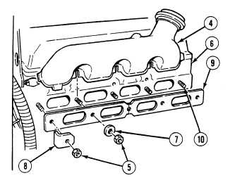
20-105. EXHAUST MANIFOLD INSTALLATION.
a.
Installation.
NOTE
Right and left exhaust manifolds are installed the same way. Right side shown.
Perform Step (1) only if studs were removed.
(1)
Using a stud remover and setter, install
studs (10) in cylinder head (6). Tighten
studs (10) to 25 to 40 lb-ft (34 to 54 N.m).
NOTE
Gaskets have a crimped side.
Crimped side faces the cylinder
head.
(2)
Position two gaskets (9) on cylinder
head (5).
NOTE
Exhaust manifold retaining
washers are special curved
washers. Curved side must
be mounted toward exhaust
manifold.
Center locknut on left side
also holds a bracket.
(3)
Position exhaust manifold (4) and three
washers (7), two crabs (8) and five
locknuts (5) on studs (10).
|