|
| |
TM 9-2320-364-34-4
21-3
a.
Disassembly.
(1)
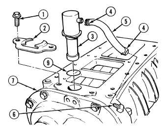
Remove two screws (1) from pressure
clamp (2).
(2)
Remove pressure clamp (2) from bypass
valve (3).
(3)
Compress lower clamp (4) and pull hose (5)
off of hose fitting (6).
(4)
Remove bypass valve (3) and hose (5) from
blower (7).
(5)
Remove two clamps (4) from hose (5).
(6)
Remove hose (5) from bypass valve (3).
(7)
Remove and discard preformed packing (9)
from bypass valve (3).
(8)
Note position of hose fitting (6) and remove
hose fitting (6) from blower (7).
Keep hands and fingers clear of
rotors. If rotors turn, fingers
may get caught between rotors
and result in injury to personnel.
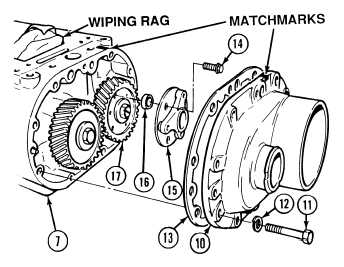
NOTE
Matchmark rear blower housing
cover and blower before removal.
(9)
Position drain pan under blower (7) to
catch excess oil.
NOTE
Wiping rag placed in blower will
prevent rotors from turning.
(10)
Place wiping rag in blower (7).
(11)
Remove nine screws (11), lockwashers
(12), rear blower housing cover (10) and
gasket (13) from blower (7). Discard
lockwashers and gasket.
NOTE
Spacer sleeves are behind hub
and will fall out when hub screws
are removed.
(12)
Remove three screws (14), hub (15) and
three spacer sleeves (16) from gear (17).
Discard screws.
|