|
| |
TM 9-2320-364-34-4
23-16
23-6. FIRST RANGE TRIMMER VALVE REPAIR (CONT).
d.
Assembly.
(1)
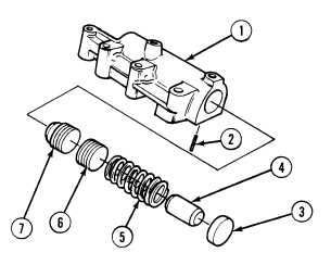
Install valve (7), plug (6), spring (5), stop (4)
and valve plug (3) in valve body (1).
Use care when replacing valve
plug. Spring behind plug is
under tension. Wear proper eye
protection to avoid personal
injury.
(2)
With the aid of an assistant, compress
spring (5) and install retaining pin (2) in
valve body (1).
(3)
Remove valve body (1) from soft-jaw vise.
e.
Installation.
All valve body screws should be
started by hand to prevent
binding. Tighten all screws to 50
percent of specified torque.
Repeat tightening sequence to
100 percent torque.
(1)
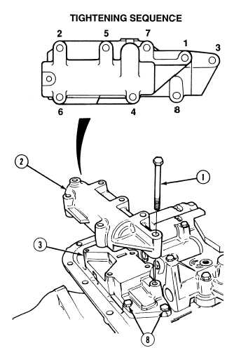
Position trimmer valve assembly (2) on shift
valve (3) with six screws (1).
NOTE
Screws tightened in Steps (2)
and (3) are screws from first
range trimmer valve and first
shift valve.
(2)
Hand tighten screws (1) and (8) in sequence
shown.
(3)
Tighten screws (1) and (8) in sequence
shown to 8 to 12 lb-ft (11 to 16 N.m).
f.
Follow-On Maintenance:
Install low oil sensor, (Para 23-5).
END OF TASK
|