|
| |
TM 9-2320-364-34-4
23-35
(21)
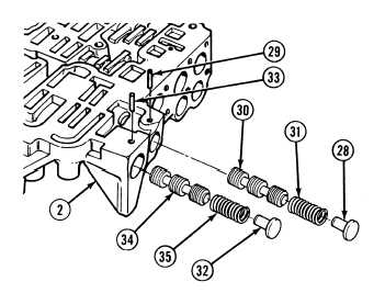
Position control valve body (2) flat side up
on clean work surface.
NOTE
Make sure 3-4 shift valve spring
is solid blue with yellow stripe.
(22)
Install 3-4 shift valve (34), spring (35) and
valve stop (32) in control valve body (2).
(23)
Compress spring (35) and install retaining
pin (33) in control valve body (2).
NOTE
Make sure 2-3 shift valve spring
is solid blue with yellow stripe.
(24)
Install 2-3 shift valve (30), spring (31) and
valve stop (28) in control valve body (2).
NOTE
Flared end of pin must extend
0.065 to 0.069 in. (1.651 to
1.753 mm) above surface of
control valve body with opening
of flare pointing in.
(25)
Compress spring (31) and install flared
spring pin (29) in control valve body (2).
|