|
| |
TM 9-2320-364-34-4
25-33
d.
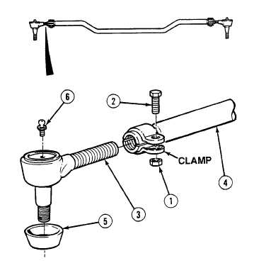
Assembly.
NOTE
Both tie rod ends are
installed the same way.
Ensure tie rod ends are
installed as noted prior to
removal.
Perform Step (1) if grease
fitting was removed.
Do not perform Steps (1)
and (2) if tie rod end is lube
for life.
(1)
Install grease fitting (6) on tie rod end (3).
(2)
Install dust cover (5) on tie rod end (3).
NOTE
Make sure that tie rod and tie rod
ends are pointed in same
direction.
(3)
Install tie rod end (3) on tie rod (4).
(4)
Position screw (2) and locknut (1) on tie rod
end (3).
(5)
Repeat Steps (1) through (4) for remaining
tie rod end (3).
(6)
Measure distance between two grease
fittings (6) on tie rod ends (3).
(7)
Turn tie rod ends (3) in or out evenly until
measurement between grease fittings (6) are
in compliance with Table 25-2.
(8)
Tighten two locknuts (1) on screws (2) to
100 lb-ft (136 N.m).
Table 25-2. Tie Rod Measurements
Tie Rod
Measurement
Axle No. 1
56-5/8 in.
Axle No. 2
54-9/16 in.
Axle No. 5
51-9/16 in.
|