|
| |
TM 9-2320-364-34-4
25-36
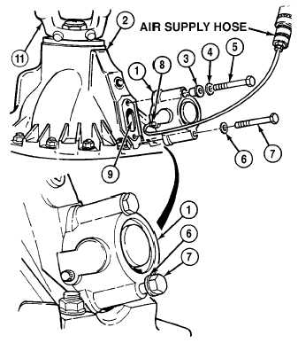
25-10. AXLE NO. 1 AND 5 LOCKING CYLINDER REPLACEMENT (CONT).
b.
Installation.
Adhesives, solvents and sealing compounds can burn easily, can give off harmful vapors and
are harmful to skin and clothing. To avoid injury or death, keep away from open fire and use
in well-ventilated area. If adhesive, solvent, or sealing compound gets on skin or clothing,
wash immediately with soap and water.
(1)
Coat mating surface of differential (2) with
adhesive.
(2)
Position locking cylinder (1) on
differential (2).
(3)
Install plastic washer (3), washer (4) and
screw (5) on locking cylinder (1).
NOTE
Screw is installed so that only
three or four threads of screw
are engaged. Screw is being
installed at this time only to
keep screw hole aligned.
(4)
Install washer (6) and screw (7) to locking
cylinder (1).
(5)
Tighten screw (5) on locking cylinder (1) to
25 to 32 lb-ft (34 to 43 N.m).
(6)
Connect air supply hose to air line fitting (8)
on locking cylinder (1).
(7)
Using air supply hose, apply air pressure
(100 to 120 psi [690 to 827 kPa]) to locking
cylinder (1).
NOTE
When locking cylinder engages
both hub gears will turn in same
direction, while rotating one
wheel.
(8)
Turn flange assembly (11) back and forth
until locking cylinder (1) engages.
(9)
Turn screw (7) slowly until screw contacts
fork (9) in differential (2).
|

