|
| |
TM 9-2320-364-34-4
25-58
Materials/Parts
Adhesive (Item 1, Appendix B)
Grease (Item 22, Appendix B)
Oil, Lubricating (Item 36, Appendix B)
Sealing Compound (Item 56, Appendix B)
Fitting, Grease (2) (Item 49, Appendix E)
Nut, Adjusting (Item 307, Appendix E)
Packing, Preformed (Item 402, Appendix E)
Seal, Oil (Item 598, Appendix E)
This task covers:
a. Removal
b. Installation
c. Follow-On Maintenance
INITIAL SETUP
Personnel Required
Two
Equipment Condition
Constant velocity joint removed, (Para 25-13)
Tools and Special Tools
Tool Kit, General Mechanic’s
(Item 240, Appendix F)
Gage, Depth, Micrometer (Item 73, Appendix F)
Micrometer, Outside, Caliper, Set
(Item 139, Appendix F)
Multiplier, Torque (Item 141, Appendix F)
Press, 60 Ton (Item 164, Appendix F)
Puller Kit, Universal, Slide Hammer
(Item 175, Appendix F)
Socket, 63 mm (Item 218, Appendix F)
Wrench Set, Socket, 3/4 in. Drive
(Item 274, Appendix F)
Wrench, Torque (0 to 175 lb-ft [0-237 N.m])
(Item 277, Appendix F)
Wrench, Torque (0 to 600 lb-ft [0-814 N.m])
(Item 278, Appendix F)
Holder, Flange (Appendix C)
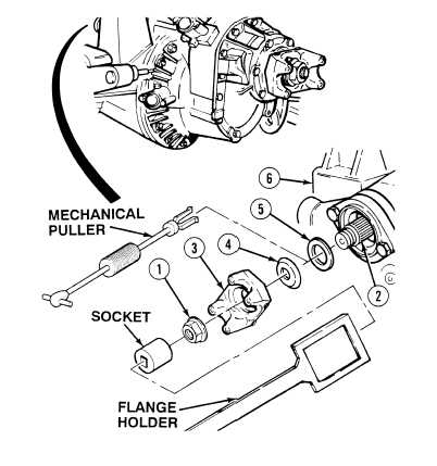
25-14. AXLE NO. 2 REAR OUTPUT ASSEMBLY REPLACEMENT.
a.
Removal.
(1)
Unstake adjusting nut (1).
(2)
With the aid of an assistant, and using
holder and socket, remove adjusting nut
from output shaft (2). Discard adjusting
(3)
Remove flange assembly (3) from pinion
shaft (2).
(4)
Separate dust cover (4) from flange
assembly (3).
(5)
Using puller, remove oil seal (5) from
housing (6). Discard oil seal.
|

