|
| |
TM 9-2320-364-34-4
25-143
(6)
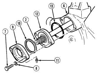
Remove two screws (7), washers (8) and
cover (9) from axle housing (6).
(7)
Remove adjusting shim (10) from cover (9).
Discard adjusting shim.
NOTE
Perform Step (8) if grease
fittings are damaged.
(8)
Remove two grease fittings (11) from
cover (9). Discard grease fittings.
(9)
Pull output shaft (2) from axle housing (6).
(10)
Remove output housing (12) from axle
housing (6).
(11)
Remove preformed packing (13) from
output housing (12). Discard preformed
packing.
(12)
Press output housing (12) from output
shaft (2).
NOTE
Perform Step (13) only if bearing
is damaged.
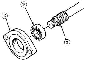
(13)
Press bearing (14) out of output
housing (12).
b.
Installation.
NOTE
Perform Step (1) only if bearing
was removed.
(1)
Apply grease to outside diameter of
bearing (14) and press bearing (14) in output
housing (12).
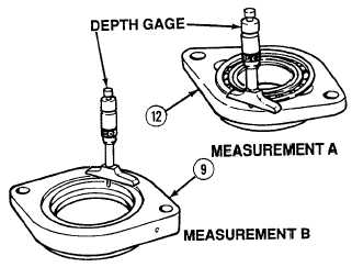
(2)
Using depth gage, measure distance “A”
between face of bearing (14) and machined
surface of output housing (12).
(3)
Using depth gage, measure distance “B”
between machined surface of cover (9) and
bottom of first land in cover.
(4)
Calculate adjusting shim thickness as
follows: (A – B) – 0.004 in. (0.102 mm)
equals shim thickness.
|