|
| |
TM 9-2320-364-34-4
25-194
25-29. AXLE NO. 4 DIFFERENTIAL ASSEMBLY REPAIR (CONT).
NOTE
Perform Step (26) if locating
pins were removed.
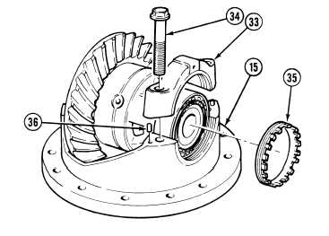
(26)
Install four locating pins (36) in housing
assembly (15).
(27)
Install adjusting nut (35), two bearing
caps (33) and four screws (34). Tighten
screws to 25 lb-in (3 N.m).
(28)
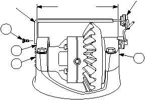
Install differential preload adapter on
bearing cap (33) with screw (31).
(29)
Position dial indicator base on bearing
cap (33) and indicator end on differential
preload adapter.
NOTE
Steps (30) and (32) adjust
bearing preload.
(30)
Tighten adjusting nut (35) to obtain a dial
indicator reading of 0.014 to 0.018 in. (0.356
to 0.457 mm).
(31)
Remove screw (31), dial indicator and
differential preload adapter from bearing
cap (33).
DIFFERENTIAL
PRELOAD
ADAPTER
DIAL
INDICATOR
DISTANCE
BETWEEN
BEARING CAPS
33
33
31
35
|