|
| |
TM 9-2320-364-34-4
28-19
This task covers:
a. Disassembly
b. Cleaning/Inspection
c. Assembly
INITIAL SETUP
Materials/Parts
Grease (Item 22, Appendix B)
Solvent, Drycleaning (Item 68, Appendix B)
Equipment Condition
Tension link on clean work surface
Tools and Special Tools
Tool Kit, General Mechanic’s
(Item 240, Appendix F)
Compressor Unit, Air (Item 35, Appendix F)
Gage Set, Telescoping (Item 69, Appendix F)
Gloves, Chemical Oil Protective
(Item 81, Appendix F)
Goggles, Industrial (Item 83, Appendix F)
Gun, Airblow (Item 86, Appendix F)
Micrometer, Outside, Caliper, Set
(Item 139, Appendix F)
Press, 60 Ton (Item 164, Appendix F)
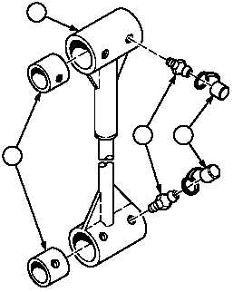
28-4. TENSION LINK REPAIR.
a.
Disassembly.
(1)
Remove four grease caps (1) and lube
fittings (2) from tension cylinder (3).
NOTE
Perform Step (2) if bushings
are damaged.
There are two different types
of weld head configurations.
If there is a shoulder machined
in the weld head between the
bushings preventing the
bushings from being pressed
out, bushings must be tapped
out from inside of weld head.
If there is not a shoulder
between bushings, both
bushings can be pressed out
from one side.
(2)
Use hammer and brass drift to remove four
bushings (4) from tension link (3).
2
1
3
4
|