 |
|||
|
|
|||
|
|
|||
| ||||||||||
|
|
 TM 9-2330-385-14
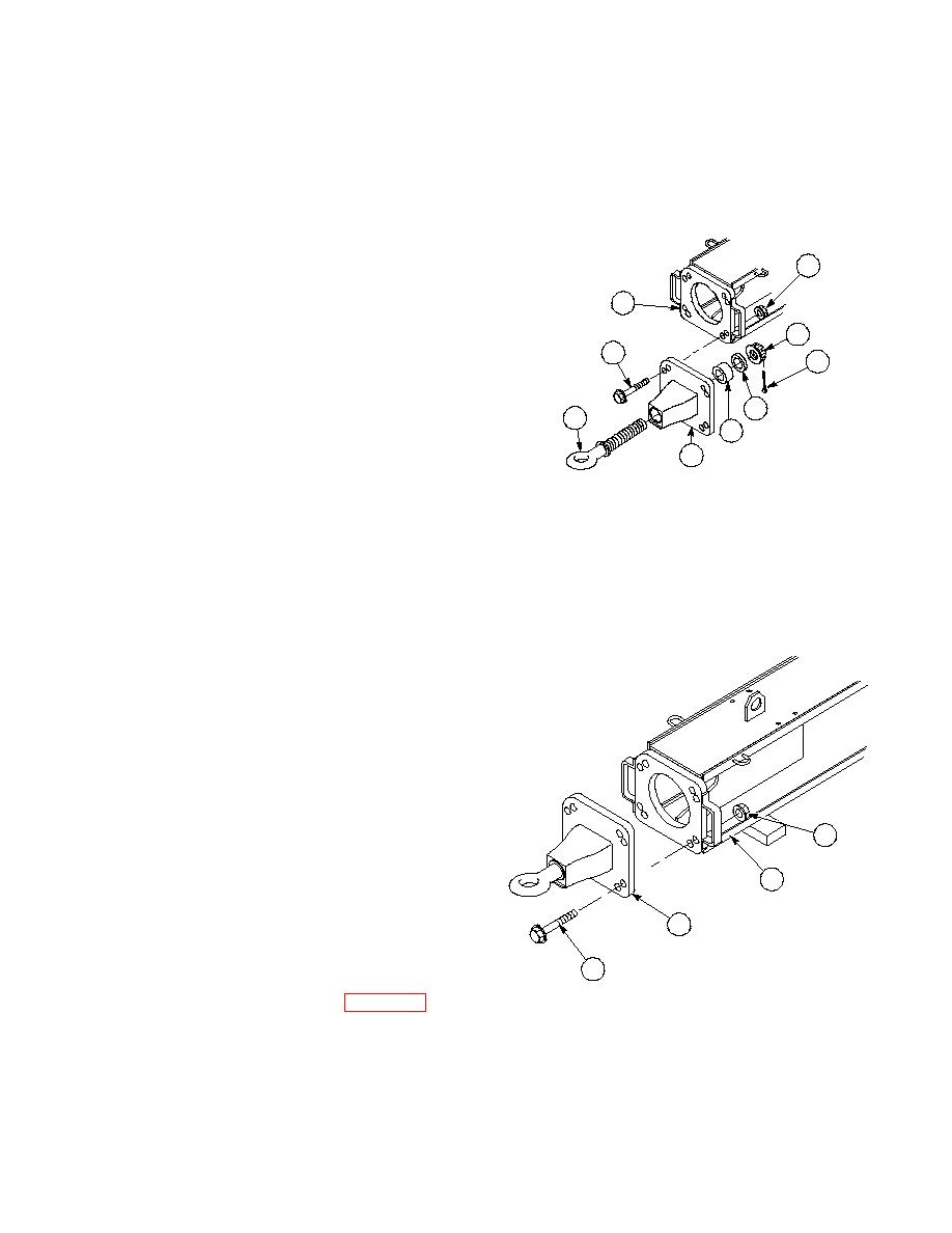
NOTE
Step (14) temporarily installs tow
ring bracket on drawbar
extension to aid in torquing of
castle nut. Use top two holes of
tow ring bracket and lower left
two holes of drawbar.
44
(14)
Install tow ring bracket (51) on drawbar
12
extension body (12) with two screws (43)
and locknuts (44). Do not tighten locknuts.
47
43
46
(15)
Position drawbar tow ring shaft (50) in
tow ring bracket (51).
48
50
(16)
Install spacer (49), washer (48) and castle
49
nut (47) on drawbar tow ring shaft (50).
51
Tighten castle nut to 2000 lb-ft (2712 N⋅m)
minimum.
NOTE
If grooves in castle nut do not
align with hole in drawbar tow
ring shaft, perform Step (17).
(17)
Tighten castle nut (47) to next slot in nut.
(18)
Install cotter pin (46) through castle nut
(47) and drawbar tow ring shaft (50).
Spread sides of cotter pin (46) against
castle nut (47).
(19)
Remove two screws (43), two locknuts (44)
and tow ring assembly (45) from drawbar
extension body (12).
(20)
Install tow ring assembly (45) on drawbar
extension body (12) with eight screws (43)
44
and locknuts (44).
12
45
43
f.
Follow-On Maintenance:
Remove wheel chocks, (Para 2-20).
END OF TASK
4-609/(4-610 blank)
|
|
Privacy Statement - Press Release - Copyright Information. - Contact Us |
