 |
|||
|
|
|||
|
|
|||
| ||||||||||
|
|
 TM 9-2330-385-14
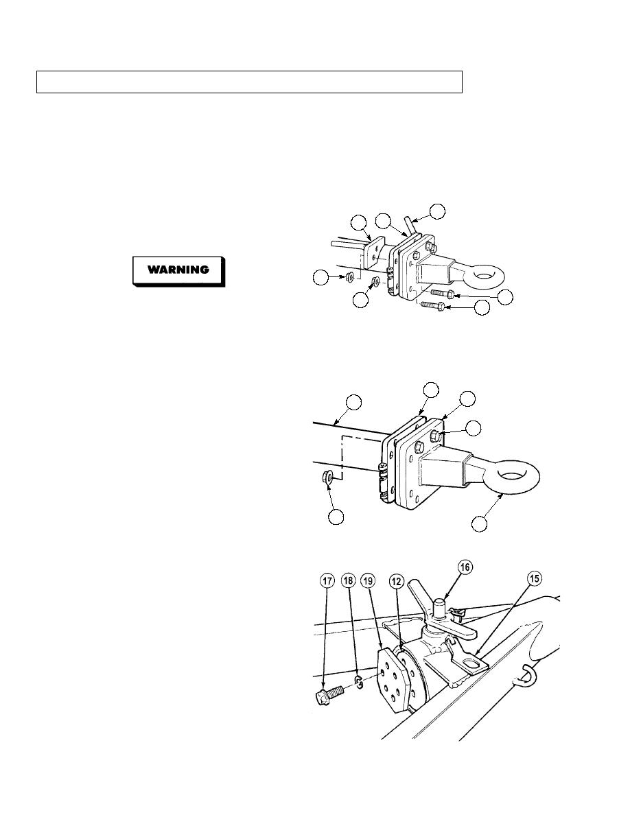
5-24. EXTENDED DRAWBAR/LIGHT BAR KIT INSTALLATION (CONT).
NOTE
Note position of handles prior to removal.
Do not remove two upper screws in Step (3). Screws are used to support tow ring to
mounting plate.
Do not discard two locknuts. Locknuts will be used in Step (6) to support tow ring.
(3)
Remove four upper locknuts (6), lower two
8
upper screws (7) and handles (8) and (9)
5
9
from plate (5) and remaining two upper
screws (7). Discard two locknuts.
6
7
10
Drawbar tow ring and mounting
11
plate will fall off when mounting
screws are removed. Care should
be taken to keep tow ring from
falling. Possible injury to
personnel may result.
(4)
Remove four lower locknuts (10) and screws
5
(11). Discard locknuts.
14
12
NOTE
7
Do not break seal between
drawbar and tube assembly.
(5)
Move plate (5) rearward along tube
assembly (12).
(6)
Position two locknuts (6) on upper screws
(7) to support tow ring (13) and mounting
6
plate (14).
13
(7)
Lift locking latch (15) and remove adjusting
pin (16).
(8)
Extend tube assembly (12) and install
adjusting pin (16) in rear hole of tube
assembly (12).
NOTE
Plate is sealed on tube assembly
and may require prying to
remove.
(9)
Remove six screws (17), lockwashers (18)
and plate (19) from tube assembly (12).
Discard lockwashers.
(10)
Remove adjusting pin (16) from tube
assembly (12).
5-86
|
|
Privacy Statement - Press Release - Copyright Information. - Contact Us |
