 |
|||
|
|
|||
|
Page Title:
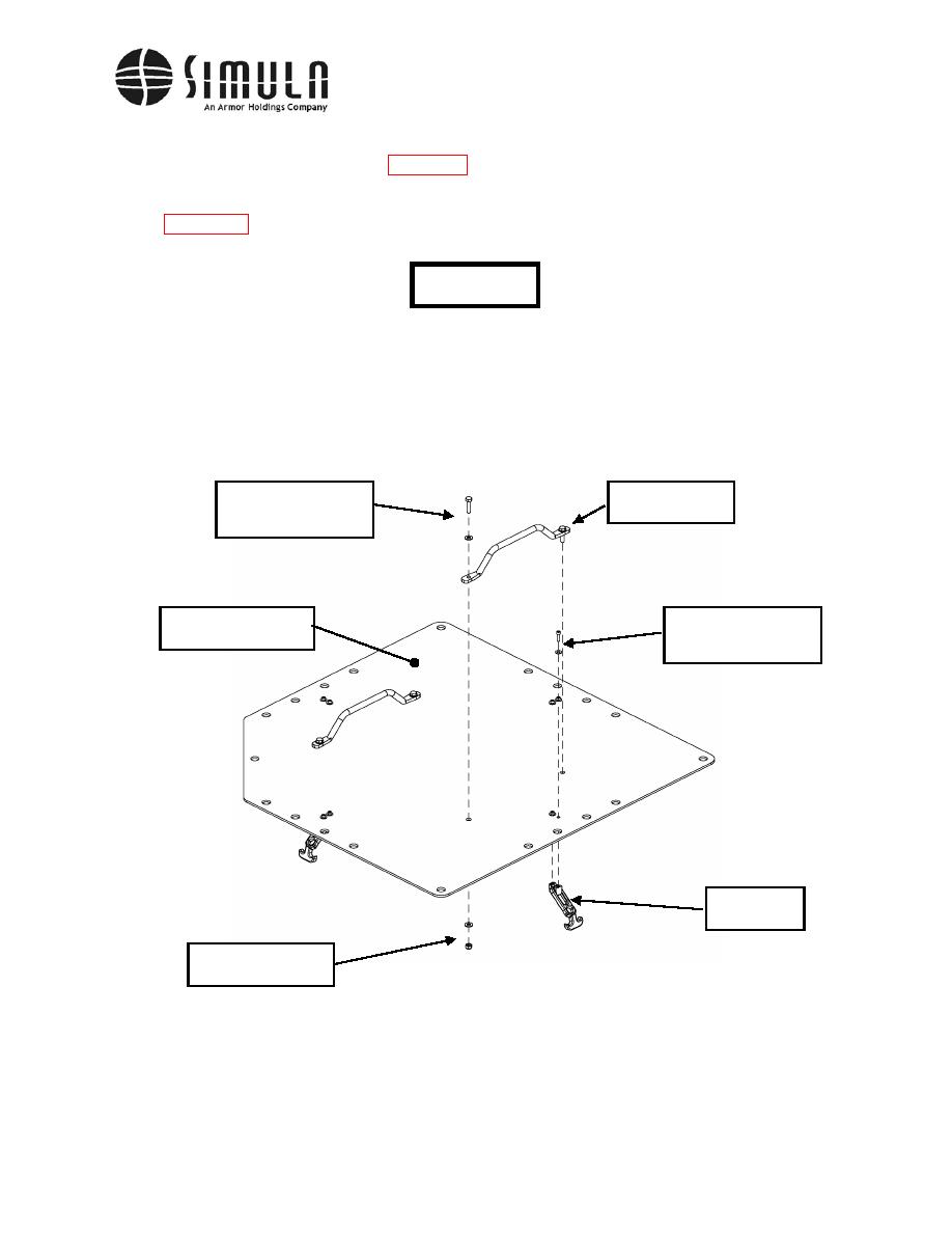
Figure 40. Escape Hatch Handle and Draw Latch installation. |
|
||
| ||||||||||
|
|
 II113300-1-103
Rev. A
c) Attach the Grab Handles (P/N 31-8-BLK) to the Escape Hatch Panel (P/N 113346-1-103)
using the hardware shown in Figure 40.
d) Attach four Draw Latches (P/N F7-51) to the Escape Hatch using the hardware shown in
CAUTION
Do not over-tighten the fasteners. The fasteners may strip the
draw latch connector if they are over-tightened.
Bolt, Hex Head,
Grab Handles,
0.312-18 x 1.250 Long,
P/N 31-8-BLK
Washer 0.312 ID
Escape Hatch Panel,
Bolt, Cap Head,
P/N 113346-1-103
0.190-24 x 0.750 Long,
Washer 0.190 ID
Draw Latch,
P/N F7-51
Lock Nut 0.312-18,
Washer 0.312 ID
e) Attach a lifting strap to the Eye Nuts (P/N 106795-1) located near the center of the
Armored Roof Assembly.
0037 00-69
|
|
Privacy Statement - Press Release - Copyright Information. - Contact Us |
