
TM 5-3990-263-13&P
0035
Table 1.
Operator Preventive Maintenance Checks and Services - Continued
ITEM TO BE
EQUIPMENT
ITEM
CHECKED OR
NOT READY/
NO.
INTERVAL
SERVICED
PROCEDURE
AVAILABLE IF:
Position remote control WINCH switch (Figure 15, Item
11) to IN until winch cable hook (Figure 15, Item 12) is
in saddle (Figure 15, Item 13).
Position HOOK ARM switch (Figure 15, Item 8) to load
position until hook arm cylinders (Figure 15, Item 9) are
extended approximately 6 inches (15 cm).
Position MAIN FRAME switch (Figure 15, Item 10) to
LOAD until main frame is in stowed position.
Position HOOK ARM switch (Figure 15, Item 8) to LOAD
until hook arm is in stowed position.
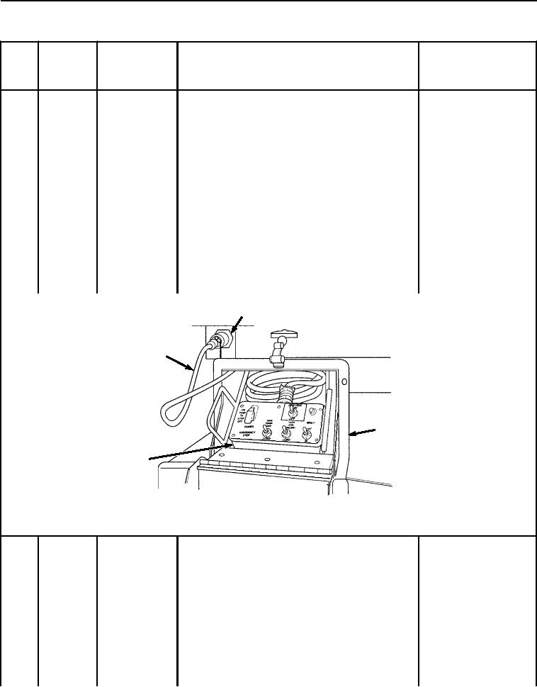
Disconnect remote control cable (Figure 16, Item 3) from
LHS receptacle (Figure 16, Item 4), and stow cable
(Figure 16, Item 3) and remote control unit (Figure 16,
Item 1) in stowage box (Figure 16, Item 2).
4
3
2
1
Figure 16. Disconnect Remote Control Unit.
NOTE
16
During
Front Pin Locks
This check must be made while bridge bay is
being loaded onto BAP.
Ensure BAP front pin locks (Figure 17, Item 1) are
Front pin locks do not
adjusted properly:
engage bridge bay front
pins.
If BAP front pin locks (Figure 17, Item 1) work
properly but do not engage bridge bay front
pins (Figure 17, Item 2), notify Field
maintenance to adjust BAP front pin locks.
If BAP front pin locks (Figure 17, Item 1) work
properly and do engage bridge bay front pins
03/15/2011Rel(1.8)root(pmcswp)wpno(I04003)