|
| |
TM 9-2320-364-20-2
2-1597
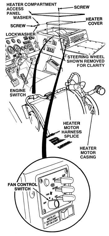
(1) Remove six screws, lockwashers,
washers and heater cover. Discard
lockwashers.
(2) Connect positive (+) multimeter lead
to orange wire at heater motor
harness splice.
(3) Connect negative (–) multimeter lead
to a known good ground.
(4) Turn ON ENGINE switch
(TM 9-2320-364-10).
(5) Turn fan control switch to high.
(a) If 22 to 28 vdc are not present,
perform Step (5) below and repair
or replace orange wire (see
schematic Fig 2-42).
(b) If 22 to 28 vdc are present,
orange wire is OK.
(6) Turn off fan control switch.
(7) Turn OFF ENGINE switch.
VOLTAGE TEST
Remove all jewelry such as rings, dog tags, bracelets, etc. If jewelry or tools contact positive electrical
circuits, a direct short may result. Damage to equipment, injury or death to personnel may occur.
(1) Set multimeter select switch to ohms.
(2) Is there continuity measured between
heater motor casing and known good
ground?
(a) If there is no continuity, repair or
replace ground wire (Para 19-13).
(b) If there is continuity, replace
heater motor (Para 19-13).
(3) Install heater cover, six washers,
lockwashers and screws.
(4) Install heater compartment panel and
eight screws.
CONTINUITY TEST
|