|
| |
TM 9-2320-364-20-4
2-3108
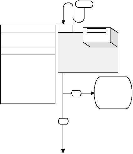
3. LOSS OF INTERFACE POWER 12 VDC.
INITIAL SETUP
1.
Repair wire 1785 (see
schematic Fig 2-76) or
notify DS
Maintenance. Verify
repair, go to Step 7 of
this Fault.
START
YES
NO
12 vdc present at polarity
protection terminal B.
Wire 1785 from 12 vdc polarity
protection to connector
MC136 terminal B faulty.
Wire 1785 from MC136 to
CB27 faulty.
Circuit breaker CB27 faulty.
Wire 1785 from CB27 to
MC136 faulty.
Wire 1785 from MC136 to
MC129 faulty.
Wire 1785 from MC136 to
MC130 faulty.
KNOWN INFO
POSSIBLE PROBLEMS
TEST OPTIONS
REASON FOR QUESTION
Voltage test.
STE/ICE-R #89
If wire 1785 from polarity
protection device to connector
MC136 is loose, faulty or
shorted, 12 vdc will not be
present at powerbox
2-37. INTERFACE TROUBLESHOOTING (CONT)
Tools and Special Tools
Tool Kit, General Mechanic’s: Automotive
(Item 74, Appendix G)
STE/ICE-R ((Optional)
(Item 3, Appendix G)
Multimeter (Item 44, Appendix G)
Jumpwire
Equipment Condition
Engine OFF, (TM 9-2320-364-10)
Parking brake applied, (TM 9-2320-364-10)
Wheels chocked, (TM 9-2320-364-10)
Are 10 to 14 vdc measured at
connector MC136 terminal B?
WARNING
Read WARNING
on Page 2-3109
|