|
| |
TM 9-2320-364-20-4
7-112
Materials/Parts
Cable Ties (Item 26, Appendix C)
Tape, Insulating (Item 88, Appendix C)
Electrical Contacts (5) (Item 25, Appendix F)
Electrical Contacts (Item 26, Appendix F)
This task covers:
a. Removal
b. Installation
c. Follow-On Maintenance
INITIAL SETUP
Materials/Parts - Continued
Electrical Contacts (Item 27, Appendix F)
Dust Boot (6) (Item 29, Appendix F)
Dust Boot (Item 30, Appendix F)
Equipment Condition
Engine OFF, (TM 9-2320-364-10)
Wheels chocked, (TM 9-2320-364-10)
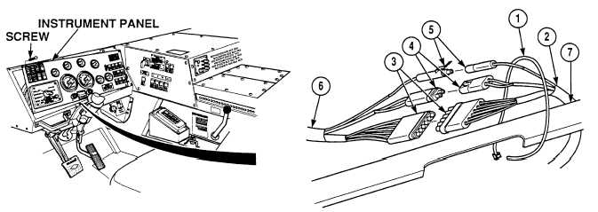
Instrument panel removed, (Para 7-13)
Steering wheel removed, (Para 14-5)
7-35. TURN SIGNAL SWITCH/HAZARD SWITCH REPLACEMENT.
Tools and Special Tools
Tool Kit, Electrical (Item 73, Appendix G)
Tool Kit, General Mechanic’s: Automotive
(Item 74, Appendix G)
Puller Kit (Item 51, Appendix G)
a.
Removal.
(1)
Remove cable tie (1) from turn signal wiring harness (2).
NOTE
Note location of wiring harness before disconnecting wire connectors.
(2)
Disconnect connectors MC7 (3), MC91 (4) and MC92 (5) from dash wiring harness (6).
(3)
Remove turn signal wiring harness (2) from under instrument panel (7).
|