Order this information in Print

Order this information on CD-ROM

Download in PDF Format


Click here to make tpub.com your Home Page

Page Title: e. Installation
Back | Up | Next

Click here for a printable version

Google


Web
www.tpub.com

Home


Information Categories
.... Administration
Advancement
Aerographer
Automotive
Aviation
Combat
Construction
Diving
Draftsman
Engineering
Electronics
Food and Cooking
Math
Medical
Music
Nuclear Fundamentals
Photography
Religion
USMC
   
Products
  Educational CD-ROM's
Printed Manuals
Downloadable Books


TM 9-2320-364-20-4      12-9 e. Installation. NOTE 
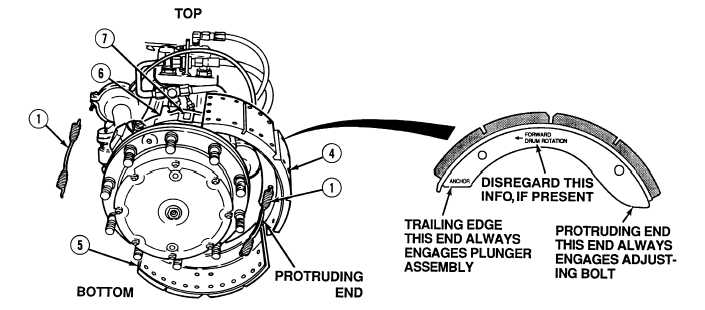
The protruding ends of brake shoe assemblies fit in slots of adjusting bolts. Only newer brake shoe assemblies are marked with “ANCHOR” at trailing edge. Axle No. 1 and 2 adjusting bolts are located on front and rear brake chambers.   Axle No. 3, 4 and 5 adjusting bolts are on a single brake chamber. Ensure upper and lower brake shoes are positioned in clips. (1) With the aid of an assistant, install front brake return spring (1) on upper and lower brake shoes (4) and (5). (2) With the aid of an assistant, position upper and lower brake shoes (4) and (5) and front brake return spring (1) on hub (6).  Shoes must fit on hub clips (7).

Privacy Statement - Press Release - Copyright Information. - Contact Us - Support Integrated Publishing

Integrated Publishing, Inc. - A (SDVOSB) Service Disabled Veteran Owned Small Business